Introduction
Additive Manufacturing (AM) offers unparalleled design flexibility, allowing engineers to create complex geometries, lightweight structures, and integrated components. However, designing for AM requires an understanding of process-specific constraints, material behaviors, and post-processing requirements. Unlike traditional subtractive (CNC machining) or formative (injection molding) processes, AM builds parts layer by layer, introducing unique design challenges and opportunities.
This white paper explores key design considerations that engineers must address to optimize part quality, mechanical performance, and manufacturing efficiency in AM.
3.1 Geometry Optimization: Leveraging AM’s Design Freedom
Traditional manufacturing methods impose strict geometric constraints due to machining tool paths, mold parting lines, and draft angles. AM removes many of these restrictions, enabling:
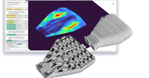
- Organic and freeform geometries → Optimizing parts for function rather than manufacturability.
- Lattice structures → Enhancing strength-to-weight ratios with minimal material use.
- Internal channels and complex voids → Facilitating fluid flow, cooling, and lightweighting.
While complexity does not increase manufacturing difficulty in AM, poorly optimized geometries can lead to:
- Warping → Uneven stress distribution can cause part distortion.
- Print failures → Unsupported features may collapse during printing.
- Excessive material usage → Inefficient designs increase print time and cost.
Best Practices for Geometry Optimization
- Use fillets and rounded edges → Reduces stress concentrations and improves print reliability.
- Optimize feature thickness → Too thin, and features may fail; too thick, and unnecessary material is used.
- Incorporate self-supporting angles → Minimizes the need for additional support structures.
By carefully considering geometric constraints, engineers can fully utilize AM’s design freedom while ensuring manufacturability and efficiency.
3.2 Layer Orientation and Anisotropy
AM processes build parts layer by layer, making mechanical properties highly dependent on print orientation. This anisotropy means that parts are:
- Strongest along the XY plane (parallel to the build plate).
- Weakest in the Z direction (perpendicular to the build layers).
Strategies for Optimizing Layer Orientation
- Align critical load-bearing features along the strongest axis → Ensures maximum mechanical performance.
- Reinforce thin walls and overhangs → Prevents delamination or deformation.
- Use ribs or internal structures → Enhances part strength without excessive material use.
Process-Specific Anisotropy Considerations
- Fused Deposition Modeling (FDM) → Pronounced layer bonding issues, requiring strategic part orientation.
- Selective Laser Sintering (SLS) & Multi Jet Fusion (MJF) → More isotropic properties due to powder sintering.
- Direct Metal Laser Sintering (DMLS) & Electron Beam Melting (EBM) → Thermal stresses introduce potential warping and cracking risks.
By proactively addressing anisotropy, engineers can optimize mechanical properties and reduce unexpected failures in AM parts.
3.3 Support Structures and Overhangs
Many AM processes require support structures to prevent warping, sagging, or collapse during printing. However, excessive supports increase material use, print time, and post-processing efforts.
Key Considerations for Support Reduction
- Minimize overhangs → Features extending beyond 45 degrees from the vertical often require supports.
- Use bridging strategies → Small gaps can be spanned without supports if kept under process-specific limits.
- Design self-supporting angles → Chamfers, fillets, and tapered surfaces reduce support dependency.
- Ensure support removal accessibility → Designs should allow for easy support removal, especially for internal features.
Process-Specific Support Considerations
- FDM & SLA → Require significant support for overhangs and intricate geometries.
- SLS & MJF → Powder acts as a natural support, reducing the need for additional structures.
- DMLS & EBM → Metal AM processes require extensive support structures to manage thermal stresses.
Reducing support structures not only lowers material costs but also minimizes post-processing labor, making production more efficient.
3.4 Surface Finish and Post-Processing
Due to the layered nature of AM, parts often require post-processing to achieve the desired surface finish, dimensional accuracy, or mechanical properties. The extent of post-processing depends on:
- Layer height and resolution → Finer layers improve detail but increase print time.
- Material and process type → Resin-based (SLA/DLP) prints are smoother than FDM or powder-based (SLS/MJF) prints.
- Build orientation → Vertical surfaces may have stair-stepping effects that require smoothing.
Common Post-Processing Methods
- Sanding and polishing → For aesthetic and functional smoothing.
- Chemical smoothing → Acetone vapor (for FDM), solvent dipping (for SLA).
- Machining and grinding → For precision fits in metal AM.
- Shot peening and heat treatments → To relieve stress and improve fatigue resistance in metal AM.
Selecting the right balance between print resolution and post-processing effort is key to optimizing manufacturing time and cost.
3.5 Internal Features and Hollow Structures
AM allows for complex internal geometries that are impossible with machining. However, these must be designed with manufacturability in mind:
- Internal channels should maintain a minimum diameter → Too small, and they may clog with powder (SLS) or fail to print properly (FDM).
- Entrapped powder must be removable → Designs must include escape holes for powder-based processes.
- Thin-walled structures risk deformation → Walls should be designed within process-specific thickness limits.
Metal AM Considerations for Internal Features
- Thermal expansion risks → Large unsupported cavities may warp due to heat buildup.
- Post-processing accessibility → Ensuring internal features can be cleaned, deburred, or polished post-printing.
By designing with internal feature constraints in mind, engineers can avoid costly print failures and excessive post-processing.
3.6 Design for Cost Efficiency in AM
The cost-effectiveness of AM is determined by material usage, build time, and post-processing requirements. Engineers can reduce cost per part by:
- Maximizing build density → Nesting multiple parts in a single print cycle (especially for SLS/MJF).
- Minimizing support material → Reducing waste and post-processing labor.
- Optimizing wall thickness → Using thin walls where structurally feasible reduces material consumption.
- Batching parts for production → Small-batch printing is most cost-effective in AM compared to traditional methods.
Injection molding becomes more cost-effective for high volumes, but AM excels in small-to-medium production runs due to its low setup costs and flexibility.
Conclusion
Optimizing designs for Additive Manufacturing (AM) requires a deep understanding of geometric constraints, anisotropy, support strategies, post-processing, and cost efficiency. Unlike traditional manufacturing, where economies of scale dominate, AM allows small-batch, customized production with unmatched design freedom.
By following best practices in AM design, companies can:
- Reduce material and production costs through optimized part orientation and lightweighting strategies.
- Enhance mechanical performance by minimizing anisotropy and using functionally integrated designs.
- Streamline post-processing by minimizing support structures and improving surface quality.
Call to Action: Optimize Your AM Designs with RapidMade
Unlock the full potential of additive manufacturing with RapidMade, Inc. Our DfAM expertise ensures your parts are cost-effective, manufacturable, and high-performance.
Visit RapidMade today for a consultation or custom quote.